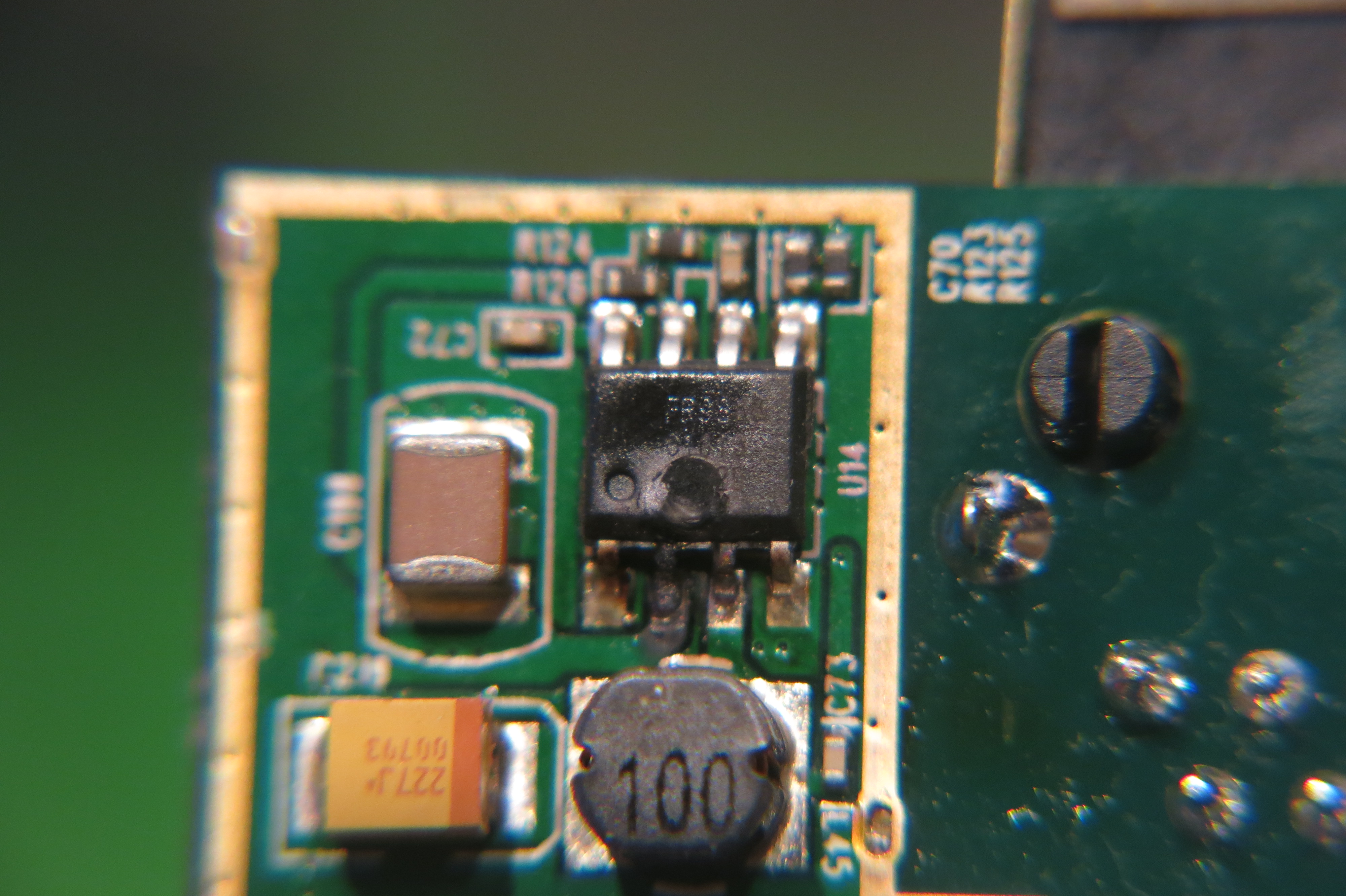
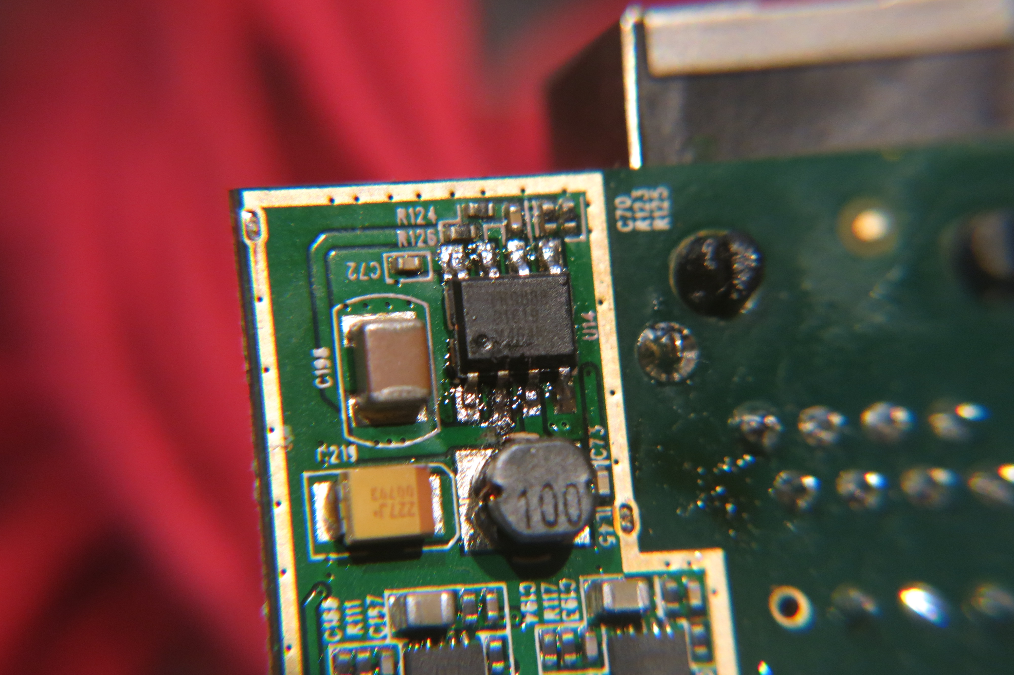
Companion note to the WiFi Pineapple Mark V repair. The dead part in that repair turned out to be a Fitipower FR9888 step-down converter — a chip I’d never heard of, on a board with no obvious markings pointing to it. Finding and reading its datasheet is what actually solved the repair, so here’s what to actually look for when you’re staring at a switching-regulator datasheet for a chip you’ve never used.
The numbers that matter first
Input voltage range (Vin) — the operating window, not the absolute maximum. A chip rated up to 23V might have a recommended operating range that’s much narrower; check both.
Output voltage / adjustable range — fixed-output parts have one number; adjustable ones (via a feedback resistor divider) give a range and a reference voltage.
Maximum output current — this is the number that tells you if a part is even a plausible match for a failed one. If the suspect chip needs to supply 2.3A and your candidate replacement tops out at 500mA, it’s not the same part regardless of how similar the pinout looks.
Switching frequency — mostly matters for the surrounding passives (inductor, output caps), not usually a smoking gun on its own, but a big mismatch versus a datasheet’s reference design is a flag that something else on the board was substituted too.
Protection features — read past the headline number
Thermal shutdown and short-circuit protection sound like they should prevent exactly the kind of failure that sends a chip to eBay in a bag of five. In practice, protection circuitry has limits: it protects against the conditions it was designed for (sustained overcurrent, sustained overtemperature), not against every failure mode. A chip rated for short-circuit and thermal protection can still die to a transient the protection loop wasn’t fast enough to catch, or to a fault path that doesn’t look like a simple overcurrent to the protection circuit at all. “Has protection” narrows the list of plausible failure causes; it doesn’t rule out the failure happening.
Reading a PCB layout recommendation as a fingerprint
When there’s no visible part number (or, as with the Pineapple’s regulator, the actual part number just wasn’t recognized on sight), the datasheet’s recommended PCB layout section is a genuinely useful cross-check. Trace widths, the arrangement of the input/output capacitors relative to the switch node, and the general footprint shape are often distinctive enough that a layout on a real board and a datasheet’s reference layout will visibly match once you’ve found the right candidate — even before you’ve confirmed the part number some other way.
Finding an unlabeled or obscure part
Package pin count and footprint first — narrows the search dramatically before you even try to match electrical specs.
Voltage/current numbers measured directly off the board (input rail, output rail, load current if you can get it) — these need to fall inside whatever candidate chip’s operating range you’re considering.
Any silkscreen or laser-marked code on the package itself, even a partial one — searchable against distributor part databases, not just general search engines.
Once you have a plausible candidate datasheet, the PCB layout cross-check above is often the deciding piece of evidence.
None of this is specific to the FR9888 — it’s the same process for any unlabeled or unfamiliar switcher on a board you’re trying to bring back to life.