Note: before we start — laser diodes at around 100mW power fall into Class 3B, which is extremely dangerous for the eyes. The infrared laser diode is even more dangerous than the red one. Infrared light is still perceived as a faint red shimmer, which tempts you to look directly into the beam, since you can’t judge the power by eye at all. Please treat this write-up with extreme caution and take full responsibility for what you do with it — I wrote this from my own experience and testing, but I take no responsibility for what you build or do based on it.
Tools needed
- Various small slotted and Phillips screwdrivers
- Multimeter with current (mA range), voltage, and diode-test range
- 3 to 5 test leads for the multimeter
- Small test clips and probe tips
- Drill and bits (if building your own mount)
Other equipment
- DVD burner to harvest (in my case a 16x dual-layer burner from Samsung)
- Lab power supply with fine voltage regulation
Possible materials for the mount
- Aluminum plate
- Angle profile
- Scrap PCB material
- 2-component epoxy adhesive
- Screws
Removal, identification and testing
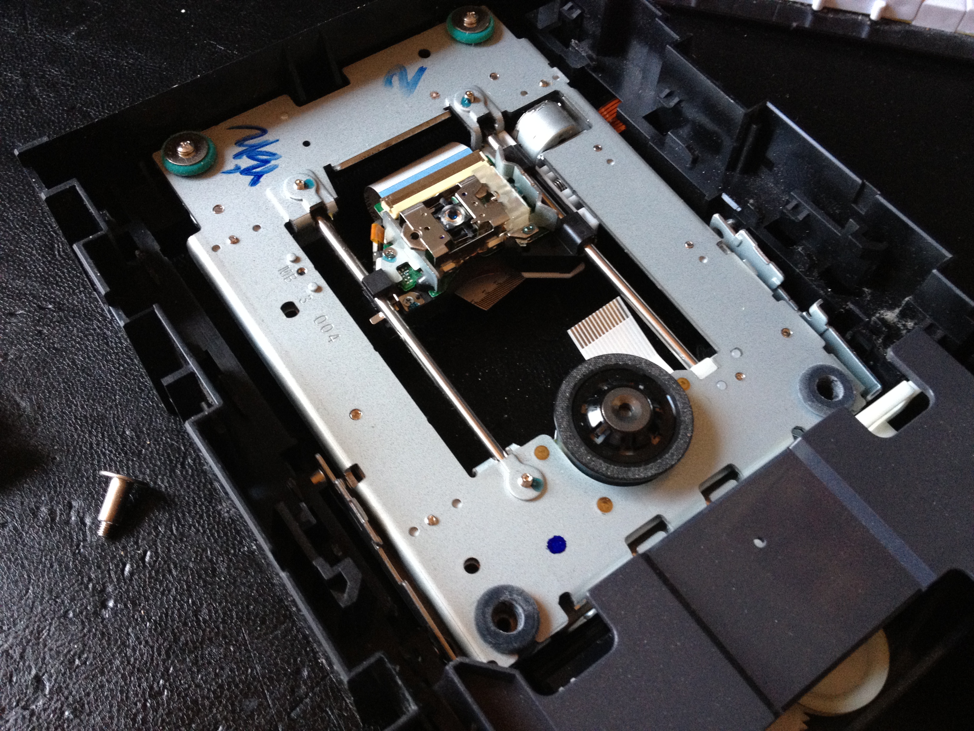
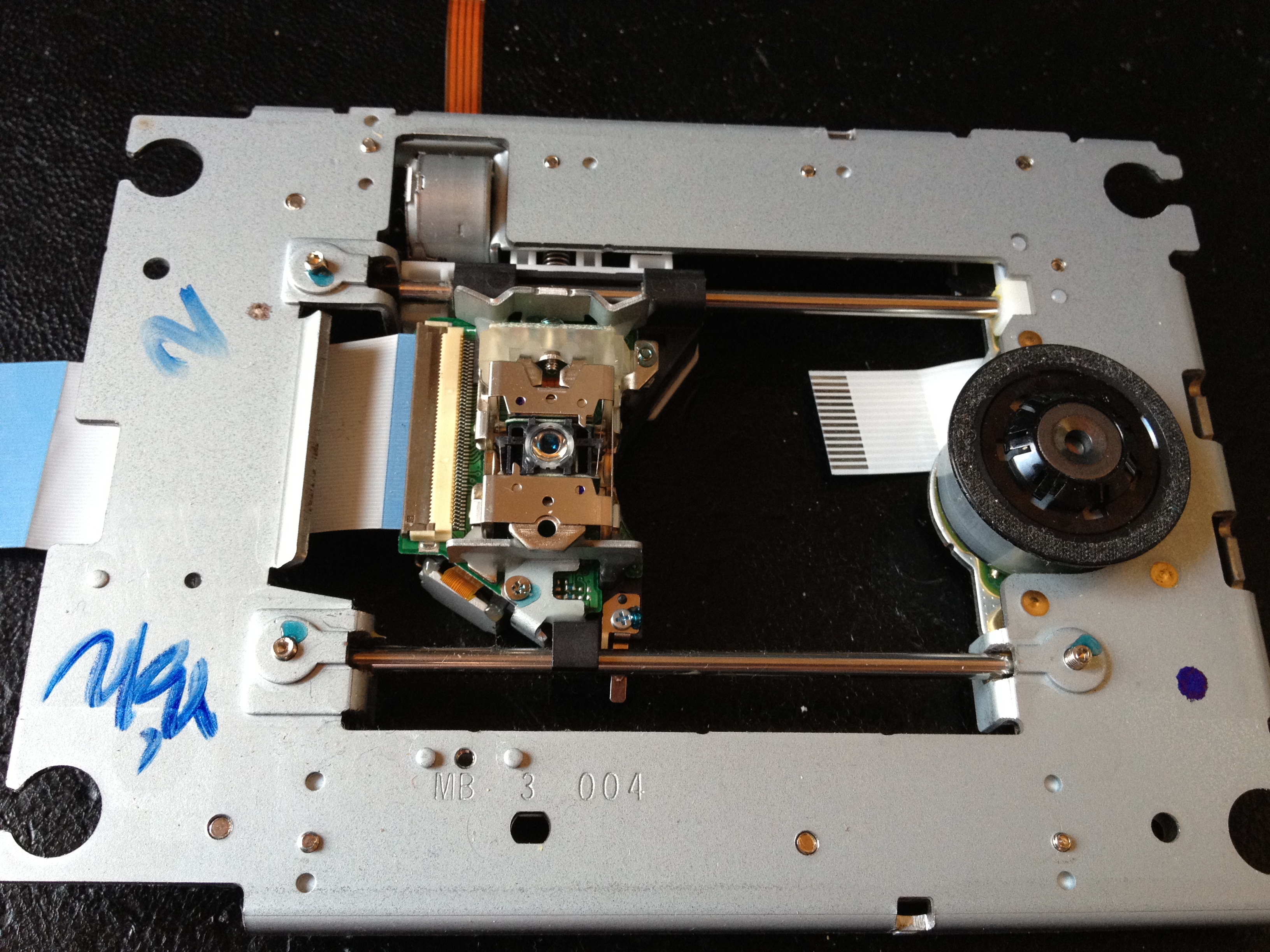
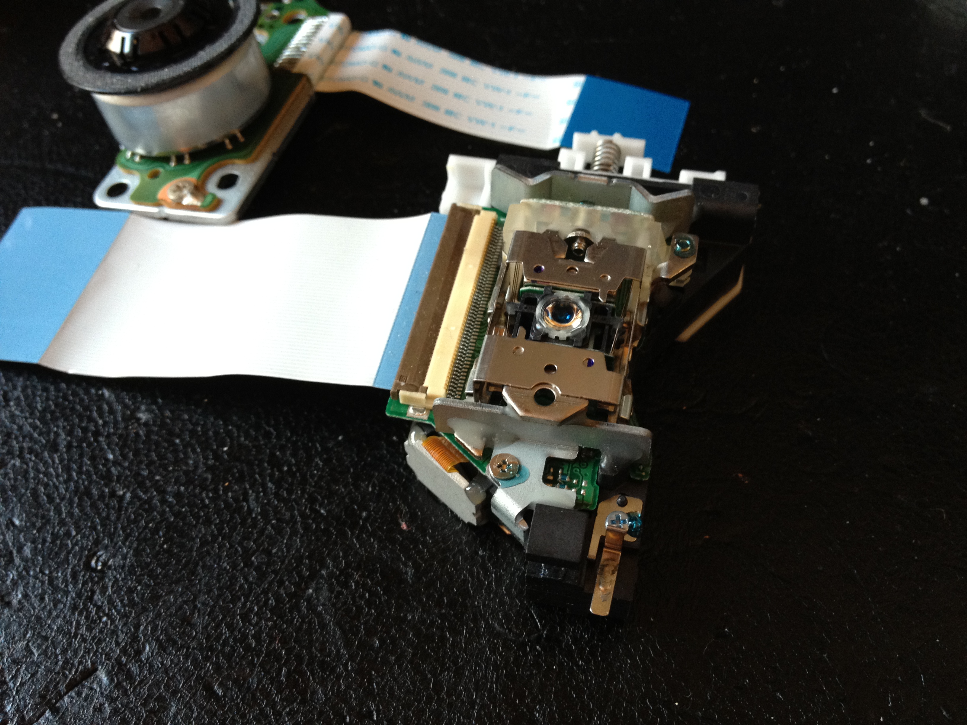
- First, remove the sled with the laser unit from the burner.
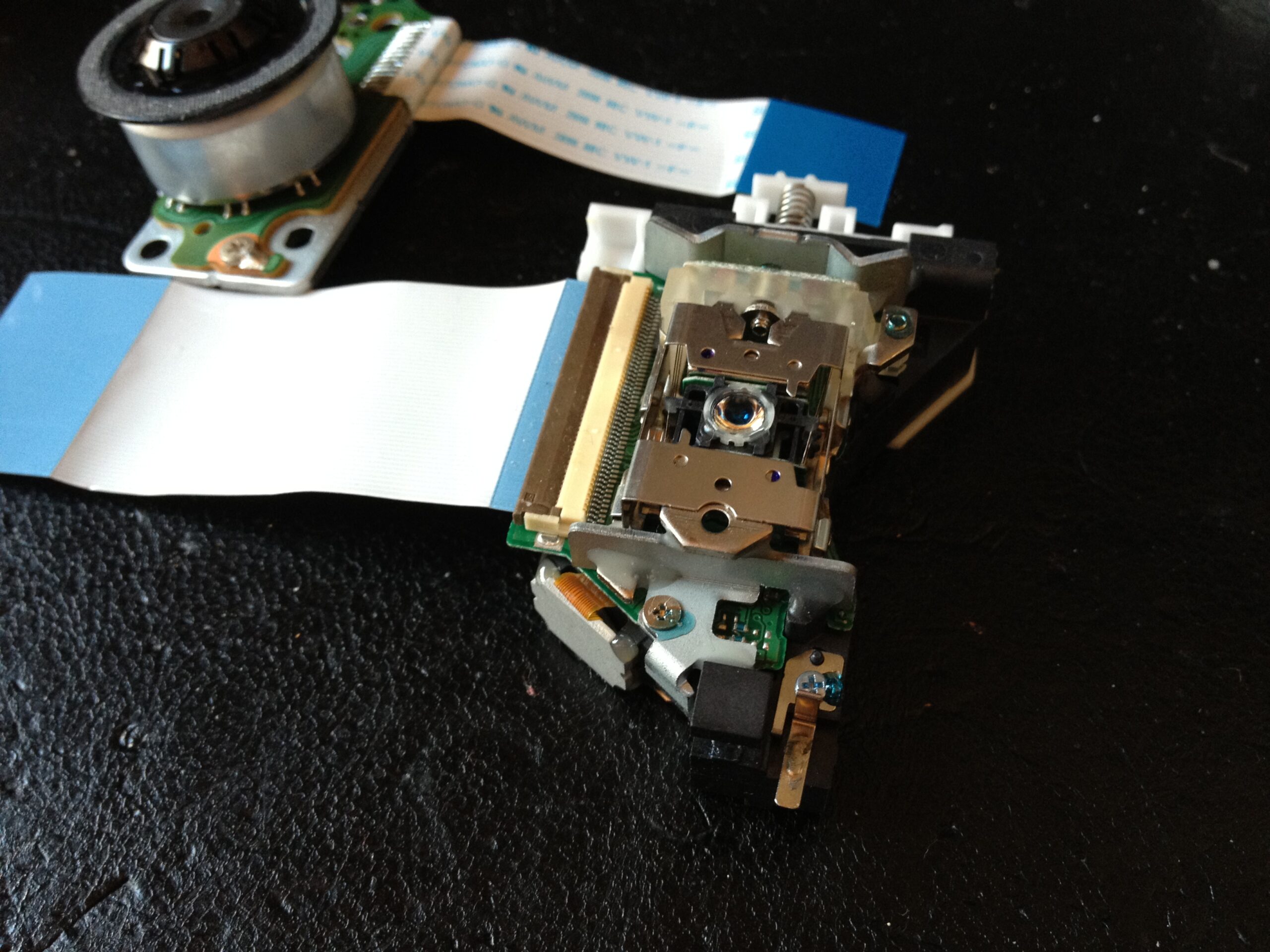
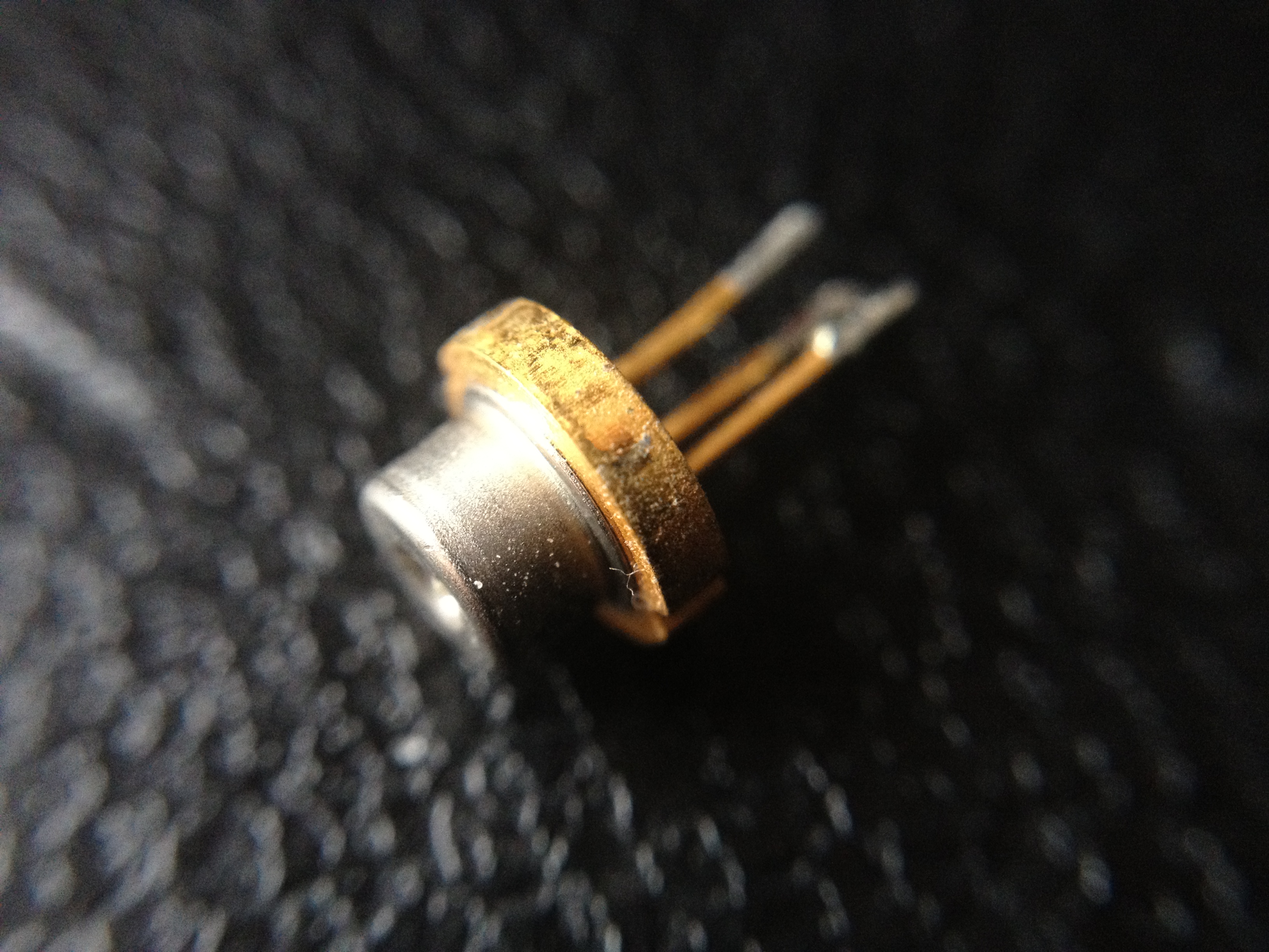
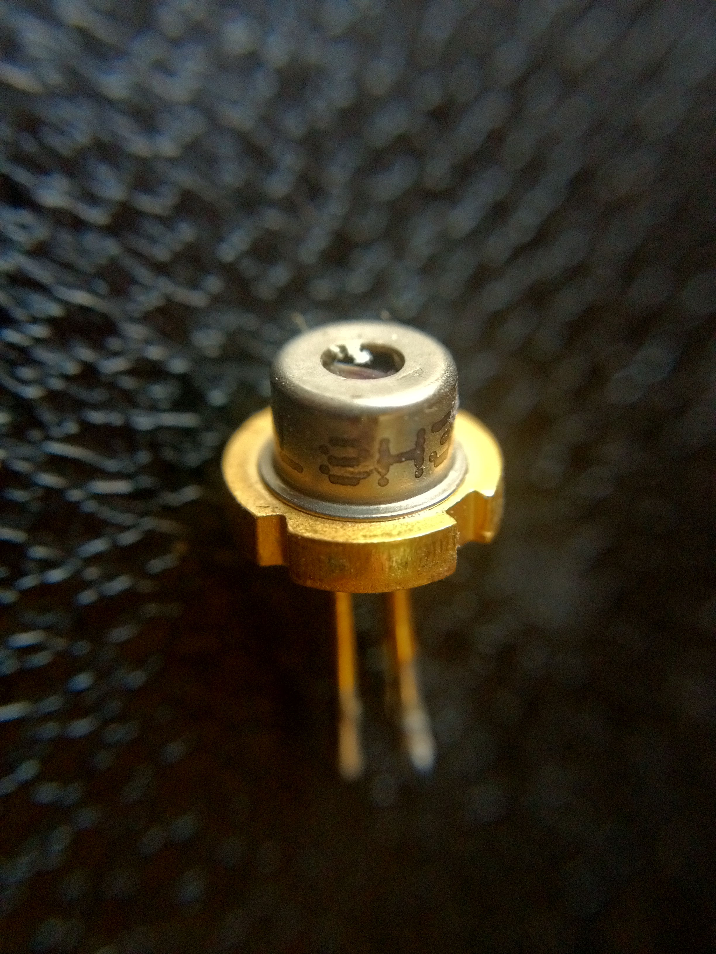
- On the side of the laser unit you’ll find the backs of the two laser diodes. They can usually be removed fairly easily along with their small retaining bracket (cut the flex cable first).
Caution: laser diodes are ESD-sensitive components. To avoid destroying them, use an antistatic wrist strap, or ground yourself repeatedly while handling them. Laser units differ between manufacturers, but the diode can usually be removed fairly easily — if in doubt, you can leave the retaining bracket attached.
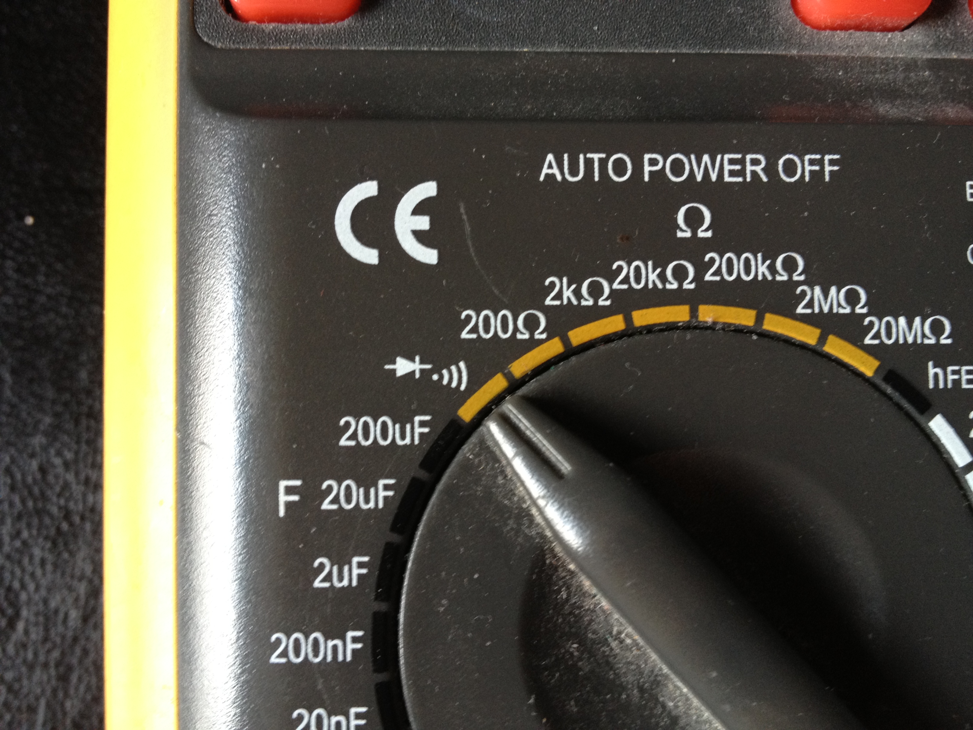
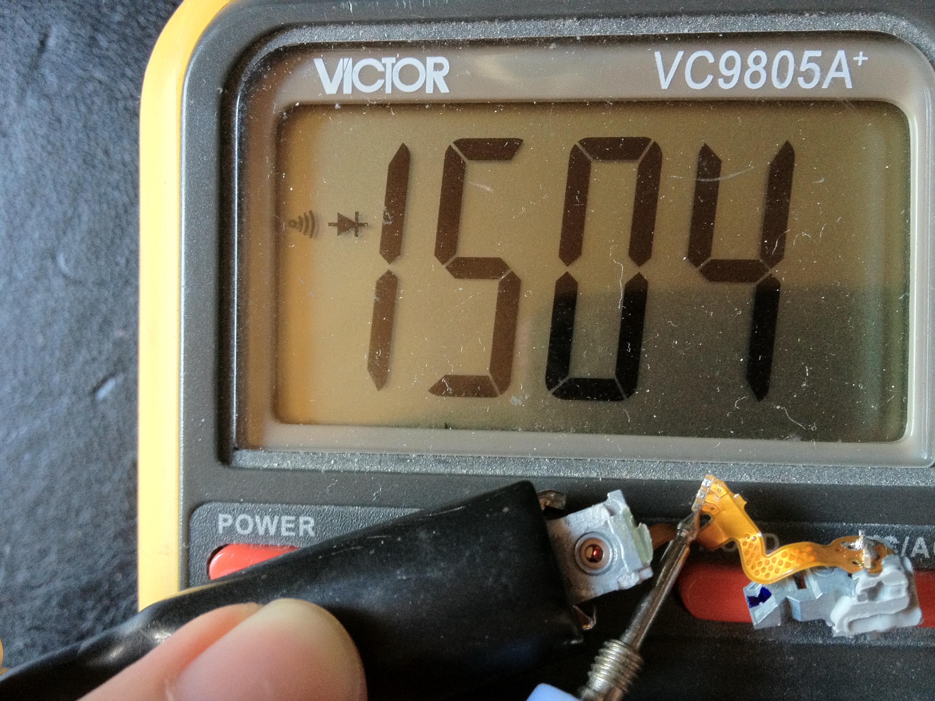
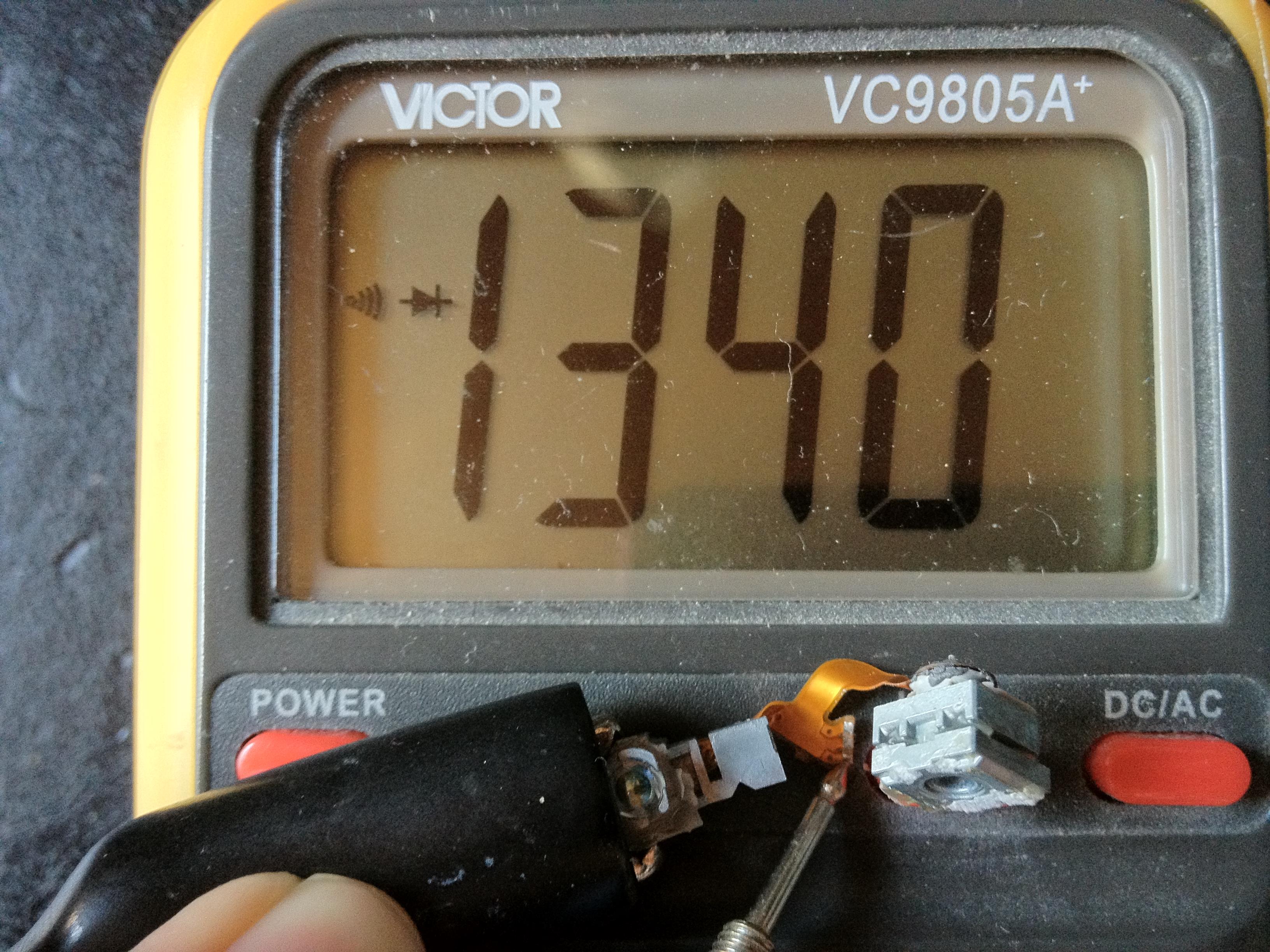
- To find out polarity and type (IR or red), connect both diodes to the meter’s diode-test range. If it shows “overflow,” reverse the polarity. One of the two diodes should light up clearly visible — that’s the red one. Forward voltage on the red diode is around 1.6V; on the infrared one it’s slightly lower. Since the meter only drives the diode with about 0.9mA in this mode, it’s safe to look directly at the die at this current.
Careful: the exception doesn’t excuse the rule — you should never look directly into a laser diode without first confirming it isn’t collimated and is no brighter than a cheap laser pointer, even at low test current. In my case the die glowed very faintly (well below the lasing threshold), which was enough to quickly identify the red diode. If you want to test at higher current right away, or if neither diode reacts to the ~1mA test current, look for the light with a digital camera instead — infrared light usually shows up on a camera sensor as an overexposed, whitish-blue glow.
Driving it up to test power
To try the identified diode properly, I put it back into the sled so heat could dissipate normally. Already at around 52mA the diode puts out several milliwatts. 150mA is the absolute maximum current for this diode — even a brief current spike can kill it. Measured maximum: 150mA at roughly 2.50V. I drove it successfully from a variable lab power supply.
One practical note on setting the current: after dialing in the diode current with the multimeter in series, do not then bridge the multimeter out of the circuit — its internal resistance is what’s actually limiting the current. Remove that resistance and the diode burns out. This only works safely if the meter’s internal resistance is a reliably high several ohms. The alternative is a series resistor with a low-resistance ammeter, or measuring the voltage drop across a known resistor and calculating the current from Ohm’s law (I = U / R) — and since higher-wattage resistors often have fairly loose tolerance, it’s worth measuring the actual resistor value first rather than trusting the printed one.
Mechanical mount and collimation
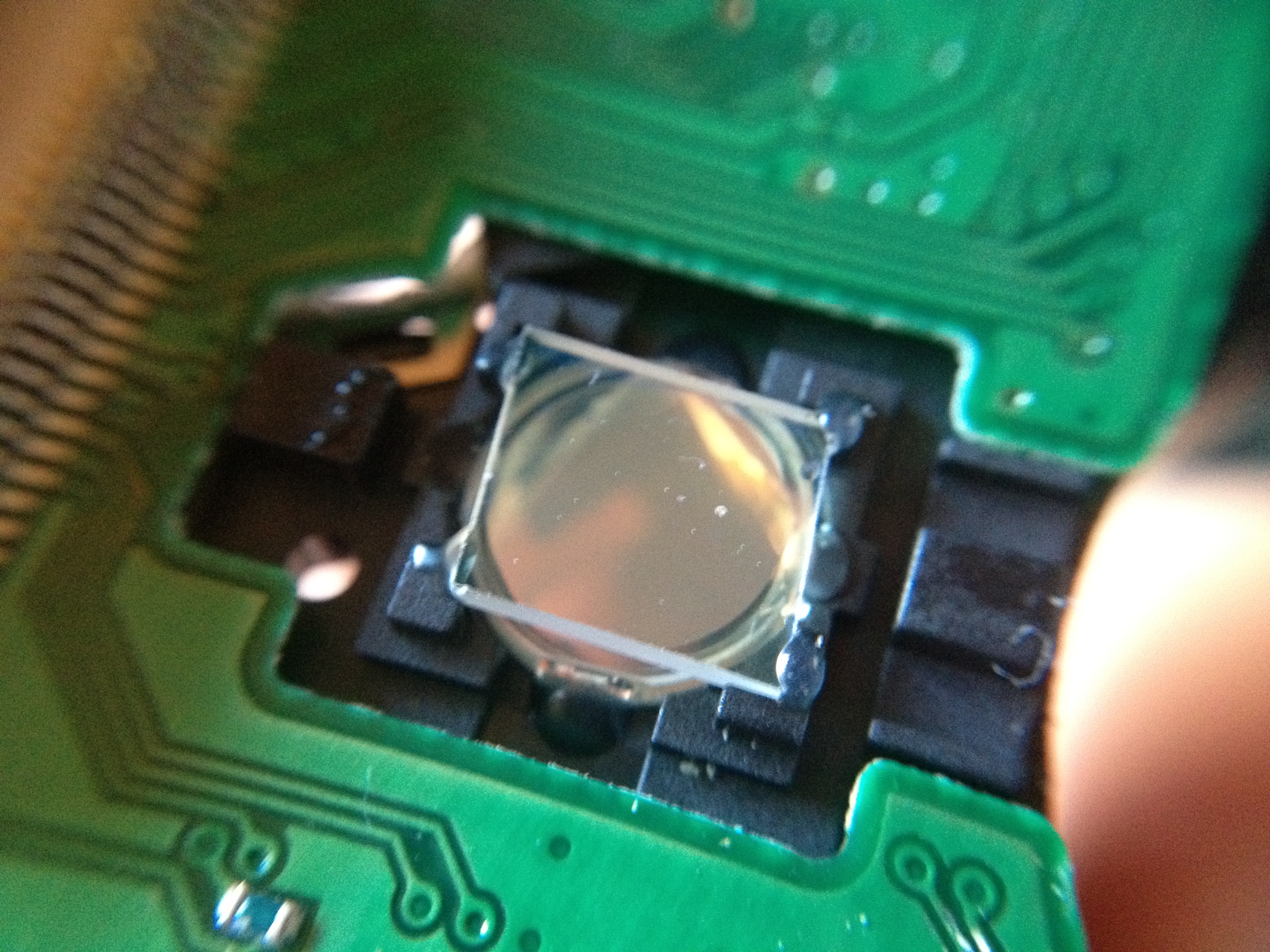
This part needs a bit of creativity. I glued the burner’s original lens onto a scrap piece of PCB, which I then glued to an aluminum plate with 2-component epoxy. After some trial and error I got the beam collimated down to about 2mm, with a divergence of roughly 2–4mRad. With the diode mounted back in the sled as before, the focal point ends up about 5mm above the lens — definitely not optimal, but good enough for a first attempt. The proper way to do this is with real lens holders that let you screw in the collimating lens and fine-adjust the diode-to-lens distance with a fine thread — in that case you also need to make sure there’s adequate cooling. When collimating, work with as little power as possible.
A driver circuit
A proper driver needs to limit the current through the laser diode very precisely — even short current spikes can send it to the semiconductor graveyard. I never finished designing one for this write-up; a lab supply with a current limit was enough for the testing above, but it’s not something you’d want to rely on for regular use. Driver circuit: still to do.
Laser diodes from optical drives, for reference
| Source | Wavelength | Power |
|---|---|---|
| DVD burner | 658nm | 2-4x: ~30mW · 8x: 50-70mW · 16x: >100mW |
| DVD burner | 780nm | 16x: >120mW |
| DVD-ROM | 658nm | 16x: ~10mW |
| CD burner | 780nm | 52x: >120mW |
| CD-ROM | 780nm | 52-56x: ~5mW |