LM35 & Arduino, noch ein Temperatursensor Beispiel
Monday, der 22. June 2015
I am planning a small project in the near future for which an Arduino UNO should measure temperatures. The standard sensor for such a task is the LM35, which is available from Texas Instruments among others. Reading an LM35 has been covered quite frequently on the internet, and in essence, it is not very difficult. Let’s do it here again, just for the fun of it.
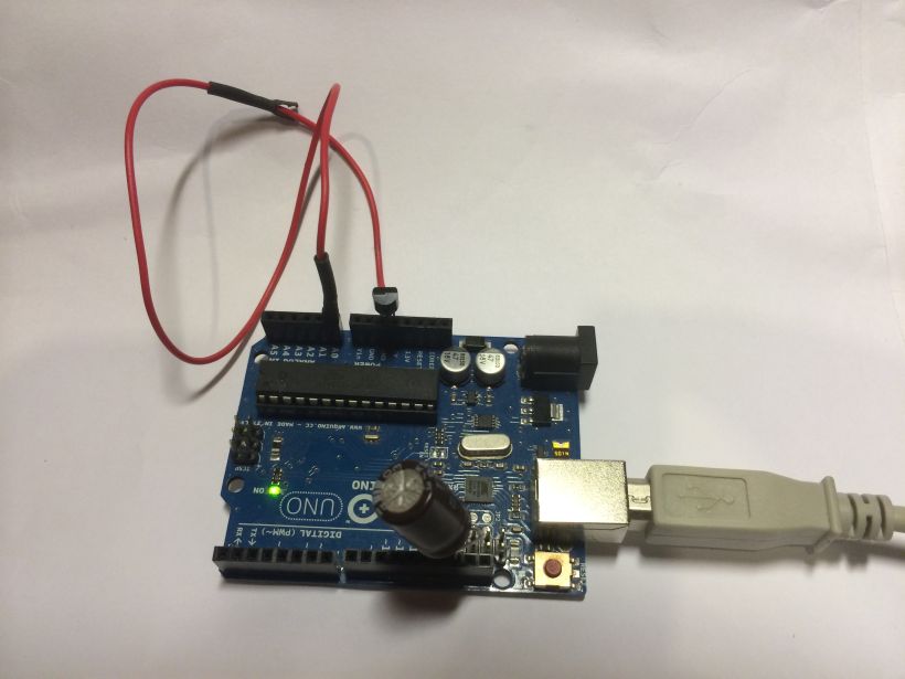
I had a vague memory from the past of how the LM35 works. Therefore, I didn’t bother looking at other people’s implementations first. Instead, I decided to invest a few minutes and see how far I could get in half an hour. The sensor has 3 pins: one for the power supply, one for ground, and one for the sensor signal. The signal is an analog voltage proportional to the temperature. A quick look at the datasheet revealed the pinout and a test circuit. It’s important to have a bypass capacitor at the AREF pin of the Arduino, or else the measurement value will fluctuate too much.
The sensor signal is measured at the A0 ‘Analog In’ pin. My first step was to use the ‘AnalogReadSerial’ example and modify it slightly. The only thing we need to do is convert the ADC value into a temperature.
[code language=”cpp”]
/* AnalogReadSerial – modefied for use with an LM35
This example code is in the public domain. */
#define ref_voltage 5.00
#define volt2temp 100
// the setup routine runs once when you press reset:
void setup()
{
Serial.begin(9600); // initialize serial communication at 9600 bits per second
}
// the loop routine runs over and over again forever:
void loop()
{
int sensorValue = analogRead(A0); // read the input on analog pin 0:
Serial.println(sensorValue * ref_voltage * volt2temp / 1024 ); // print out the value you read
delay(1); // delay in between reads for stability
}
[/code]
The raw sensor data is in the range between 0 and 1023. 0 represents 0 volts, and 1023 represents the full reference voltage. So, we need to convert SensorValue into an actual voltage and then into the desired temperature. For this, I multiplied the measurement value by 5.0 and then divided by 1024, using the good old rule of three. The reason I multiplied by 5.0 instead of 5 is to implicitly (incidentally) convert the result into a float value. Finally, the intermediate result is multiplied by a proportionality factor to obtain the temperature. According to the datasheet, 10mV corresponds to 1 °C, or in other words, 1 volt corresponds to 100 °C. All of this is done in one line of code:
[code language=”cpp”]
Serial.println(sensorValue * ref_voltage* volt2temp / 1024 );
[/code]
The code works, but the result is a bit strange, to say the least, and disappointing in terms of accuracy. With a room temperature of 23.7°C, the Arduino outputs 29.3°C. When you think about it, the reference voltage of the Arduino UNO is standard at 5V. Since the ADC gives us 1024 values in between, this gives us an accuracy of about 0.00488V per step. Thus, the ADC’s resolution is 0.48°C, which is slightly better than the sensor’s minimum accuracy.
As it turns out, the significant discrepancy is due to the reference voltage. In my case, it was about 4.17V (power supply via a USB hub). Once I corrected the reference voltage, I got values of 23.62°C. Looks good so far!
Obviously, the external reference voltage is not good enough. But it basically works. Time to look around. Most other implementations I’ve seen are similar.
For example, gunnarherrmann.de additionally encodes the pin used for measurement with its keyword, which is smart in case multiple sensors are used. He also averages his values to filter out statistical outliers. However, his code is somewhat strange. First of all, constants should always be declared with #define and never as a variable. This simply saves RAM. He also uses an array to store consecutive measurement values, which is also a waste of RAM. The measurements averaged are 1 second apart, so the temporal resolution is not really great anymore. I don’t really like the code repetition either.
Other websites like playground.arduino.cc or adafruit.com have similar approaches. I saw a few examples that use delays between measurements, which I think are not necessary. Most interestingly, there is the use of the internal reference voltage, which is about 1.1V. Since the ADC divides the reference voltage into 1024 steps, this results in a voltage resolution of almost 0.001V. Since the LM35 is only meaningful for temperatures below 100°C, which corresponds to a voltage of at most 1V, we stay below the reference voltage. A higher voltage can potentially damage the ADC.
In the end, I solved it like this:
[code language=”cpp”]
/*
AnalogReadSerial – modefied for use with an LM35
This example code is in the public domain.
*/
#define LM35 A0 //Sensor Pin
#define ref_voltage 1.08 //actually measured AREF Voltage
#define volt2temp 100
#define average_count 50
#define prop_constant ref_voltage* volt2temp / 1024 /average_count
// the setup routine runs once when you press reset:
void setup()
{
Serial.begin(9600); // initialize serial communication at 9600 bits per second:
analogReference(INTERNAL);
}
// the loop routine runs over and over again forever
void loop()
{
int sensorValue = 0;
// read the sensor multiple times and sum up the readings
for (int i = 0; i < average_count; i++)
{
sensorValue += analogRead(LM35);
}
Serial.println(sensorValue * prop_constant); //print out the value you read
delay(100); // delay in between reads for stability
}
[/code]


